Shakti Prabha


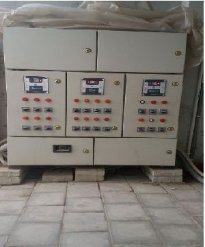
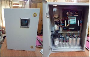
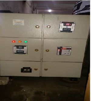
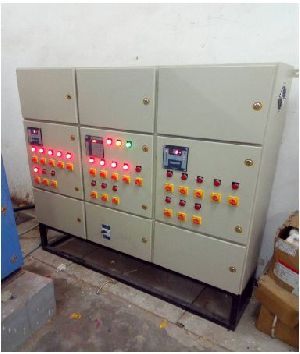
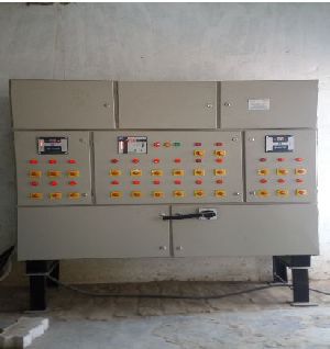
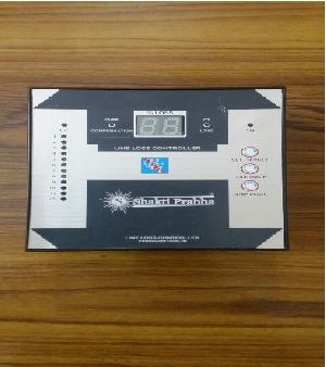
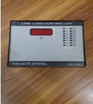
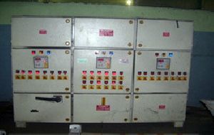
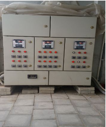
Energy Saver Line Loss Controller

Business Type Manufacturer, Supplier, Retailer

Preferred Buyer From

Location Anywhere in India

All Power Factor correction System being used globally in market have been designed and are applicable on balance three phase electric circuit i.e. balance power factor, balance voltage and balance load. It confirms, all conventional power factor correction system (APFC Panels) are inefficient on unbalance electric circuit.

Virtual power factor is a new invention in electrical engineering. Conventional power factor correction systems published and in use do not include correction of unsymmetrical voltage and current vector, unbalance power factor, unbalance voltage and unbalance load in three phase electrical system. Voltage/Current Vector become unsymmetrical mainly due to unbalanced load and displacement of neutral. In unbalance system, lagging/leading reactive power, average value of power factor is recorded which result power factor closer to unity inspite of presence of accountable reactive energy in circuit. In such an unbalance electrical system, KWH and KVAH both consumption are recorded on higher side. Thus power factor of unbalance system is not actual but it is virtual.


Energy Saver-Line Loss Controller ensures cancellation of total reactive power of each phase independently of unbalance electric circuit which includes following characteristic of electrical parameters in three phase electric circuit.

  1. Unbalance Power Factor – Different Power factor of all three phases
  2. Unbalance Voltage – Different voltages of phase to neutral of all the phases.
  3. Unbalanced load – Different values of Load in Amp. of all the phases of three phase supply.
  4. Vector Unbalance – Unsymmetrical voltage and current vector due to displacement of neutral by unbalance load.


1.UNBALANCED POWER FACTOR
Unbalanced Power factor in three phase electric circuit is created by the following three methods –

  • Characteristic of Load being used - Single phase load and three phase load like melting furnace, Mig, Seam and Arc Welding etc create unbalancing of Power factor in three phase electric circuit.
  • Unbalancing of Power Factor is created by unbalance inductive load of electric circuit in three phases become different and further at unbalance load neutral displacement takes place which make power factor lagging/ leading in three phases, average power factor closer to unity by conventional APFC panel.
  • Unbalancing of Power Factor due to service Transformer in three phase electric circuit is new invention. In present times unbalancing of power factor by Transformer is dominating as Transformer quality loose cores, winding, poor quality laminations and other manufacturing defect, power factor of Transformer at NO load is found very poor and unbalanced of the order 0.20 and 0.03 in three phases being recorded in main meter. At full load also there is prominent unbalancing of power factor in three phases.


For correction of power factor unbalancing by method a, b and c conventional Automatic Power Factor (APFC) having three phase delta capacitors are being used which create lagging / leading power factor in circuit, resulting average power factor recording closer to unity in meter.

2.UNBALANCED VOLTAGE
Voltage of all the three phases with Neutral is not equal; it is termed as unbalance voltage. Main reasons of unbalance voltage are detailed as below: -

  • Main supply voltage is unbalance of three phases.
  • Due to some defect in L.T./H.T. winding of Power Transformer
  • In all normal condition variation of voltage permissible limit is not as per I.S.S.
  • Neutral displacement due to unbalance load.

Voltage unbalance in all the three phases of electric circuit is created by above methods a, b, c and d. Power Factor correction is being done by conventional Automatic Power Factor Controller (A.P.F.C.) having three phase capacitors. Fixed quantity of Capacitor is switched on by APFC at a time on all the three phases, which result leading/ lagging reactive power in three phase circuit. Due to displacement of neutral average power factor is recorded closer to unity in Main Meter.

Present new invention of Energy Saver – Line Loss Controller switch on required bank of Three phase capacitor and Single phase capacitors automatically on each phase therefore appropriate selection of KVAR capacitors of each phase nullifies reactive power due to unbalance voltage of all three phases.

3.UNBALANCED LOAD
Mainly there are two type category of unbalanced load in three phase electric circuit.

  • Unbalancing of Load on secondary (L.T.) side of Power Transformer. This unbalancing of Load depends on the characteristic of  Plant Load like unbalance reactive load, unbalance transient variable reactive load for the processes single phase load and three phase Load of buildings, etc, industrial load of Plastic Industry, Stone Crushers, cold storage, Fabrication Auto Plants, Mig Welding, Seam welding, Arc welding plants so many others. Three phase motors are generally old and rebound after a couple of times have weak insulation because of which impedance differs of three phases which create unbalancing of load. Conventional Automatic Power factor controllers basically designed for balance electric circuit are installed having three phase delta capacitors. Power Factor recording in main meter is closer to unity but there are higher energy losses in electrical circuit proportional to gravity of unbalancing of Load.
  • Unbalancing of Load on Primary Side (H.T.) of Power Transformer feeding to heavy Industries like Induction furnace, Steel Plants, Cement Factories etc .which cannot control power factor by Conventional APFC panels on primary of Power Transformer having three phase delta H.T. Capacitors. Power Factor is closer to unity in case of unbalance electric three phase circuit but appreciable cumulative electric losses due to unbalance electric circuit are there.

Present new invention of Energy Saver – Line Loss Controller corrects Power Factor balance and close to unity of each unbalance Load phase by use of Star H.T. capacitors operative by Tri Power Factor Controller. It results reduction in demand and consumption.

4.UNSYMMETRICAL VOLTAGE AND CURRENT
At unbalance load, neutrals have tendency of displacement which contribute unsymmetrical voltage and current vector and there is no 120 degree phase difference between Y, R and B. Application of conventional Auto Power Factor Controller improves average power factor closer to unity, due to lagging / leading reactive energy remain present in circuit. It increases demand and consumption of three phase electric circuit. Practically it is observed that KVA demand and KVAH consumption reduction is not in ratio of power factor improvement close to unity, as it is much on lower side. Further study has confirmed above phenomena on account of neutral displacement which is true.

Details Required

  • Name & Address of Consumers
  • Email
  • Mobile No.
  • Contracted Load
  • Supply Voltage
  • Process and Load details in short
  • Detail of Electricity Bill

Summer months    KWH consumption    KVAH consumption    Recorded Demand
Winter months       KWH consumption    KVAH consumption    Recorded Demand

  • Load in Amp. – Phase R, Y & B
  • Problems and Solutions required
Read More...

  • Additional Images

  • Model A Line Loss Controller

  • Model A1 Line Loss Controller

  • Model A2 Line Loss Controller

  • Model B Line Loss Controller

  • Model C Line Loss Controller

  • Percentage Relay

  • Voltage Relay

Looking for "Energy Saver Line Loss Controller" ?

Piece

Explore More Products


Close

Raise your Query

Hi! Simply click below and type your query.

Our experts will reply you very soon.
WhatsApp Us